The "Goldberg" -revisited-

Use of these circuits is subject to the laws of your country of residence.
This information is provided for educational purposes and/or authorized usage only.

___________________________________________________________________

Fred Nachbaur's"Goldberg" (4 tubes)
Here's the ultimate crystal-controlled low-power AM transmitter. It incorporates a superior audio preamplifier stage, allowing better control of loop feedback. It also includes an effective RF amplifier stage which boosts the maximum output by 5 dB, to about 10 milliwatts. This is enough to improve the range by about 73%, or be enough to drive a linear amplifier.

Fred's AM Transmitters can be seen here:

http://www.xminusone.com/am/Fred Nachbaur/transmitters.htm

___________________________________________________________________

Evan's Improvements to the original design

New 6v Tube lineup - 12AT7, 6GY6, 12AU7, 6AL5

The real difference/s between Fred Nachbaur's "Goldberg" original and this redesign:

  1. Replaced the 6BE6 with a 6GY6. The 6GY6 oscillator is a sharp-cutoff pentode tube with dynamic sound quality that's superior to the 6BE6.
  2. I've given you a second (optional) RF Output stage. It has more output power than the original and sounds fantastic. See the second schematic below.
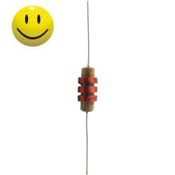
  3. Replaced the HC51U, metal can crystal. Now using a Soviet built 1000khz crystal vacuum tube.
    The vacuum tube crystal connects up without any circuit changes being made. This adds a really cool look to the transmitter and it performs very well.
  4. To improve the quality and linearity, I've updated the oscillator circuit.
  5. I've modified the common-cathode amplifier by adding one additional component.
    (Regarding this addition please see the "Modifications section" below.)
  6. I added the two capacitors to the feedback circuit which allows the potentiometer to act more like a pre-emphasis control. This was mentioned by Fred in his original posting. I find after adding these components, that it maintains its linearity and accomplishes the stated goal nicely. However, after listening to this for a while, I removed these capacitors. I find that I prefer listening to it without this modification.
  7. I've upgraded the split bi-polar power supply. For good measure, I've added two chokes and two additional filter capacitors.
  8. The two resistors & two capacitors in the filament circuit helps eliminate hum injection and cathode RF leakage.
  9. I've simplified the RF output, using a 100uh RF choke, and tuning the RF output with the variable 50pf capacitor on the antenna side.
  10. Now using a single power transformer: Hammond 269AX
  11. This TX is built on a project box that is 6"x 8".

Final thoughts:

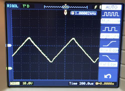
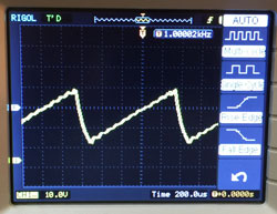
This is a real nice TX. It is a bit more complex to build, but the end result is satisfying. Fred, said that his Goldberg is best peaked/tuned with an oscilloscope. I would agree with this.

Fred said it was the only one he listened to after building his original. With the modifications I've made to linearize the audio even more, I can only believe this new "-revisit-" would have improved the experience.

Check out the video at the bottom.

___________________________________________________________________

Click on the image below for a larger schematic.

TX Power Output 73% more - as mentioned by Fred?

No, I cannot verify this. Of course, Fred was referring to "The Gypsy" his 3 tubes TX. I find that this MU follower RF output configuration produces a small clean waveform. However, using a single section of the 12AU7 setup in a more traditional way produces better results than the MU follower.

So, if you're looking for more horsepower and you're only using a wet noodle antenna (A wire used as a radio antenna.) you might wish to try the RF output circuit shown below instead of the MU follower. I recommend the JJ EL84 or a 6BQ5.

On the print below please notice that I've added a little negative bias to the grid of the EL84, which increases the modulated power.

On this TX, I've installed a variable inductor RF output coil (28uH - 90uH) which allows me to match the antenna impedance. The one I'm using is the Miller 6056 however, I suggest mounting this coil on a small daughter board so that the legs of the coil are not stressed when it is installed. Optionally, the Miller 6039 works just fine. You will need to use an oscilloscope to adjust this TX appropriately.

NOTE: If you cannot find such a variable inductor try using a fixed 68uh RF inductor, and add a 50pf variable capicitor on the antenna side for peaking the output. The results will be close enough at the design frequency of 1.63mhz.

The print below shows the TX with a modified RF output using an EL84.

___________________________________________________________________

The schematic/s above always show the latest updates.

The pictures below may not show every update.

Click on any image below for a larger picture.

The ribbon cable you see goes to the LED's installed in the tube sockets.

All on a single 6" X 8" top!

___________________________________________________________________


To answer your FAQ's


Lessons learned!

Do not use a radial lead power inductor on the plate of the oscillator tube, use a true RF choke. Antique Electronic Supply will sell you what you need. If you use the radial lead choke, which is smaller and looks better, the oscillator may not be playing at it's FULL potential.


Power Supply Design

Fred Nachbaur said:

Within the power supply there are individually decoupled power supply filter sections. The rationale behind this was to provide good decoupling between the three tubes involved, whilst keeping the voltages reasonably high.

Fred Nachbaurs said:

Note that this transmitter uses about twice the B+ voltage of any of the previous designs. This is to accommodate the higher requirements of the mu-follower RF amplifier, and to help linearize the performance of the short-tail-pair differential audio amplifier. However, the supply is set up as a split (bipolar) supply, which allows us to ground-reference the output tank coil.

http://www.radiomuseum.org/forum/hi_fi_am_transmitter.html

R8,R9,C19,C10 eliminated hum injection and cathode RF leakage.


Modifications to Fred Nachbaur's common-cathode amplifier

http://www.tubecad.com/2005/April/blog0042.htm

.....................The easiest solution is to place an additional plate resistor in the circuit. This resistor should be shunted to ground through a large-valued capacitor to ensure the benefits of the common-cathode amplifier. Many solder slingers do not bother adding the capacitor, introducing the Miller-effect capacitance and losing gain as a result. Laziness, stinginess, trendiness, and ignorance are the usual suspects.

The common-cathode amplifier shown above is nicely fleshed out: the diode protects the triodes at turn-on, when the cathodes are cold and not conducting. Once the they are conducting, the diode falls out of the circuit, as it becomes reverse-biased and no longer conducts. The decoupling capacitor is in place, which will shield the input from a inverted gain at the plate. A feedback loop returns a small portion of the output signal to the inverting input, stabilizing the gain, lowering both distortion and output impedance.

NOTE: I originally installed the diode shown above, however I removed it. I found that tubes from several manufacturers would not operate correctly in Fred's audio amplifier circuit with this diode installed. I also find that the right tube choice makes an incredible difference in the performance of this transmitter. I recommend the Raytheon Black Plate - 12AT7 tube, or if you can find one, a Mullard 12AT7.


Modifications to Fred Nachbaur's pentagrid oscillator

L1 & L3 are 2.5mH RF Chokes. This increases the output of the oscillator noticeably.


Modifications to the feedback circuit

Modifying the circuit as shown below changes the feedback pot to act more like a pre-emphasis control. Instead of feeding back all frequencies equally, the feedback network now favors the low frequencies, causing a greater gain reduction at lower frequencies, hence pre-emphasizing the higher frequencies.

___________________________________________________________________

1936 - Model 4586 Sears Silvertone radio listening to the,

Goldberg -revisited-
(with an EL84 RF output)